Saturday, April 19, 2014

ECG Interpretation Review #86 (Regular WCT – VT – SVT – DeWinter T Waves – Aberrant Conduction – Capture Beats)


Interpret the ECG shown in Figure 1 — obtained from a 53-year old man who presented to the ED (Emergency Department) with new-onset chest pain of 1 hour duration. He was hemodynamically unstable with a systolic BP ~60 mm Hg at the time this ECG was obtained.
  • What is the rhythm in Figure-1 likely to be?
  • How certain are you of your answer?
  • What is your differential diagnosis?
  • Clinically — What would you do?

Figure 1: ECG obtained from a patient with new-onset chest pain. BP = 60 systolic. What is the rhythm? What would you do? 


------------------------------------------
Interpretation of Figure 1: There is a fairly (but not completely) regular WCT (Wide-Complex Tachycardia) at a rate of ~150/minute. Normal P waves are not seen. The patient is hemodynamically unstable. Therefore — VT (Ventricular Tachycardia) should be assumed until proven otherwise. Immediate cardioversion is indicated. Do you agree?

A number of questions are raised by this ECG and clinical scenario.
  • How certain can we be that this rhythm is VT?
  • Does it matter if we are not certain about the diagnosis — given that the patient is hemodynamically unstable?
  • What specific features of this ECG and long lead II rhythm strip favor VT as the diagnosis?
  • What features suggest this might not be VT?
  • How will we know?
------------------------------------------
NOTE: This case was sent to me for my opinion. I did not see the patient. Before I reveal my sequential thought process — You might contemplate your answers to the above questions.
------------------------------------------


MY ANSWERS: My initial assessment of the ECG in Figure 1 was as stated above — that the rhythm was a fairly regular WCT (Wide-Complex Tachycardia) at a rate of ~150/minute without normal P waves — therefore VT until proven otherwise. Since the patient was clearly hemodynamically unstable — 1st priority was to cardiovert the patient regardless of what the rhythm might be. This was done. That said — I was not certain of the diagnosis.
  • While the QRS complex during the tachycardia seen in Figure 1 does appears to be wide — QRS morphology is not particularly suggestive of a ventricular etiology. Instead — it is more suggestive of an LBBB (Left Bundle Branch Block) pattern, in that a monophasic upright R wave is seen in both leads I and V6; and the QRS is predominantly negative in lead V1.
  • The problem is that QRS morphology of LBBB-type during a WCT (Wide-Complex Tachycardia) rhythm is usually non-diagnostic — and, may be due to either VT or SVT (SupraVentricular Tachycardia) in which the reason for QRS widening is preexisting bundle branch block, aberrant conduction, or something else that produces baseline QRS widening.
  • Several morphologic features IF seen are especially suggestive that a WCT rhythm is VT. These include: i) Extreme axis deviation (ie, completely negative QRS in either lead I or lead aVF); ii) Completely upright R wave in lead aVR (without any q or Q at all in aVR); iii) Completely negative (or almost completely negative) QRS in lead V6; and/or iv) Global concordance of QRS complexes in the precordial leads (in which the QRS is either all positive or all negative in each of the 6 precordial leads). As helpful as seeing any of these features is in favoring VT — not seeing them is of no help in diagnosis. None of these features are present in Figure 1.
  • Although an LBBB pattern per se is not helpful in ruling in or out VT — a supraventricular etiology is more likely IF downslope of the S wave in leads V1,V2,V3 is very steep. In contrast — slurring or slight delay in the downslope of the S wave in anterior leads is more suggestive of VT (due to greater likelihood of initial delay in activation when origin of the WCT is from the ventricles). Downslope of the S wave in leads V1,V2,V3 in Figure 1 is indeed very steep. Noticing this made me question if this rhythm was really VT ...
  • The rhythm in Figure 1 is not completely regular. This is clearly evident on the long lead II rhythm strip. That said — VT is not always precisely regular. Given what looked to be regular R-R intervals between beats #2-3; 3-4; 6-7; 7-8; 10-11; 11-12; 16-17; 17-18; 20-21; 21-22 — I did not feel this rhythm was quite irregular enough to render a diagnosis of AFib (Atrial Fibrillation) — though this was in my differential given the absence of normal P waves.
  • QRS morphology changes for beats #9, 13, 15, 19 and 23 in the long lead II rhythm strip of Figure 1. Are these capture beats or fusion beats that further support the likelihood that this rhythm is VT? I thought they might be.
Having spent precious seconds contemplating the pros and cons reflected in the above bullets for “VT or no VT” — I was left with the following thoughts: i) I was not certain of the rhythm diagnosis; ii) Given uncertainty — VT should be presumed until proven otherwise; and iii) Given hemodynamic instability with high likelihood that this instability was caused by the tachycardia — immediate cardioversion was indicated regardless of what the rhythm turned out to be.


------------------------------------------
The POST-Conversion Rhythm: As stated above — the patient whose rhythm was shown in Figure 1 was hemodynamically unstable. The patient was treated for VT — and, was shocked twice. This resulted in the rhythm shown in Figure 2.
  • What is the post-conversion rhythm in Figure 2?
  • Do you agree with the arrows that we have marked out in the long lead II rhythm strip? — in which red arrows were used for P waves we can see, and open arrows for the P waves we presume are present but hidden within the QRS complexes of beats #3,6,9 and 11?
  • KEY Question: Does the ECG in Figure 2 change your opinion about what the rhythm was in Figure 1?
  • Clinically — What do you think happened in this case?

Figure-2: ECG obtained after the patient was shocked. What is the post-conversion rhythm? Does this ECG change your opinion about what the initial rhythm was in Figure 1? (See text).


------------------------------------------
MY ANSWERS: Presumably — the arrows in the long lead II rhythm strip in Figure 2 do reflect conversion to a fairly regular sinus rhythm (with open arrows representing P waves hidden within the QRS complexes of beats #3,6,9 and 11). Some of these P waves are conducting — as evident from the constant PR interval preceeding beats #2,4,5,7,8 and 10. But many of the other P waves that should be conducting are not conducted. We therefore interpret the rhythm as high-grade 2nd Degree AV Block.
  • Recognition that the P waves of beats #2,4,5,7,8 and 10 are conducted is KEY to retrospective determination of the rhythm in Figure 1. This is because we now know what the QRS should look like during a supraventricular rhythm. For example — Look directly above beat #7 in the lead II rhythm strip in Figure 2. Note that the main reason the QRS complex in simultaneously-occurring leads V1,V2,V3 is wide — is due to dramatic ST segment depression that evolves into a peaked T wave. The same is true when we look directly above the sinus-conducted beat #10 — in that we see dramatic ST depression in leads V4,V5.
  • Note that QRS morphology in the long lead II rhythm strip in Figure 2 is different for beats #1,3,6,9 and 11. That these beats truly look different than conducted beats #2,4,5,7,8 and 10 — is perhaps best seen by looking in leads V5 and V6 — where it is obvious that there are 2 differently shaped QRS complexes. Beats #1,3,6,9 and 11 are PVCs.
  • Knowing that beats #2,4,5,7,8 and 10 are conducted — allows us to assess these conducted beats in other leads on this post-conversion ECG for ST-T wave changes. Doing so reveals a picture highly suggestive of DeWinter T waves! That is — We see subtle-but-real ST elevation in leads aVR and aVL — and significant J-point ST depression in leads V1-thru-V5 that leads into peaked T waves (at least in leads V2,V3). In a patient with new-onset severe chest pain — this ECG pattern is highly suggestive of acute proximal LAD (Left Anterior Descending artery) occlusion.
To check out the above theory — I made Figure 3 by superimposing on the ECG from Figure 1 (BLUE border) a series of inserts showing sinus-conducted complexes from leads II; aVR,aVL; V1,V2,V3; and V5,V6 in Figure 2 (RED borders). Apart from perhaps slight additional ST-T wave widening (attributable to tachycardia) — QRST morphology during the initial “wide tachycardia” in Figure 1 is very much like QRST morphology of sinus-conducted complexes in Figure 2.
  • In retrospect — I think the rhythm in Figure 1 was supraventricular all along. The illusion of “QRS widening” was probably produced by marked ST-T wave abnormality from the DeWinter T wave pattern. An additional component of ST depression may have been added in Figure 1 attributable to the supraventricular tachycardia (which is a known cause of ST depression).
  • Rather than fusion or capture beats — I suspect the underlying rhythm in Figure 1 may have been sinus tachycardia (with sinus P waves hidden within preceding T waves) — and, with beats #9, 13, 15, 19 and 23 being PVCs. This premise is supported by Figure 2, which indeed shows PVCs of similar morphology to that of beats #9,13,15,19,23 in Figure 1.

Figure-3: ECG I made by superimposing on the ECG from Figure 1 (blue border) a series of inserts showing sinus-conducted complexes from leads II; aVR,aVL; V1,V2,V3; and V5,V6 in Figure 2 (red borders). Note similarities in QRST morphology during after the tachycardia (See text).


------------------------------------------
Putting It All Together: I suspect the reason for this patient’s new-onset chest pain was acute proximal LAD occlusion (DeWinter T wave pattern). He was probably in sinus tachycardia in Figure 1 with cardiogenic shock from his evolving acute STEMI. In the “retrospectoscope” — one can question the initial cardioversion. That said — given the initial ECG picture and hemodynamically instability that for all-the-world seemed the result of the tachycardia — initial shock was indicated. This case is unusual and highly instructive because QRS widening seemed not to be due to preexisting bundle branch block or aberrant conduction — but rather to dramatic ST-T wave changes from a DeWinter T wave pattern.
------------------------------------------
Case Conclusion: Following the ECG in Figure 2 — the patient developed progressive bradycardia followed by PEA arrest. He was resuscitated with Epinephrine and intensive CPR. A pulse was temporarily regained, in association with the ECG shown in Figure 4. He remained hypotensive despite pressor therapy. He arrested again — and could not be resuscitated.
  • In view of previous tracings — How would you interpret the ECG shown in Figure 4? The patient was not responsive and was hypotensive at the time this tracing was recorded.
  • What is beat #6?

Figure-4: ECG obtained following resuscitation from PEA arrest. The patient was hypotensive. In view of previous tracings in this case — What is the rhythm?


------------------------------------------
Interpretation of Figure 4: If simply shown the ECG in Figure 4 and told that this ECG was obtained during a code from a patient who remained hypotensive — VT would clearly be the presumed rhythm diagnosis. However — We feel a fairly convincing case has been made that the original rhythm in Figure 1 was supraventricular and not VT. Given close resemblance of QRST morphology between wide beats in Figure 1 and Figure 4 — We strongly suspect the rhythm in Figure 4 is again supraventricular (perhaps sinus tachycardia?) with QRS widening still due to the DeWinter pattern.
  • Morphology of beat #6 in Figure 4 is consistent with morphology of other beats felt to be PVCs in Figures 1 and 2.
------------------------------------------
Acknowledgment: I am greatful to “CZ” — who sent me these tracings and allowed me to use this case for teaching.
------------------------------------------
- For more information — GO TO:


  • See Sections 08.0, 09.0 (excerpted from ACLS-2013-ePub) — for pdf review on differentiation between SVT vs VT –  
  • For review on DeWinter T Waves — Check out our ECG Blog #53.
------------------------------------------

Thursday, March 6, 2014

ECG Blog #85 — 23yo with Palpitations

     
The ECG and lead II rhythm strip shown in Figure-1 — was obtained from a 23-year old man who presented with “palpitations”. He was presumably healthy prior to the occurrence of this arrhythmia — and he was hemodynamically stable at the time this ECG was recorded.
  • Is the rhythm more likely to be VT (Ventricular Tachycardia) or SVT (SupraVentricular Tachycardia) with aberrant conduction?
  • What factors favor one or the other diagnosis?
  • Adenosine was initially tried as treatment. When this was unsuccessful — Verapamil was tried. Comment on this selection of treatment.

Figure-1: ECG and lead II rhythm strip obtained from a 23-year old male with palpitations. He is hemodynamically stable. Is this more likely to be VT or SVT with aberration?


Interpretation of Figure-1: 
The rhythm appears to be a regular WCT (Wide-Complex Tachycardia). Unfortunately, angling of the ECG paper has introduced slight irregularity in measured intervals — but the “theme” of this smart phone photo is that of a regular WCT rhythm.
  • The rate of this regular WCT is just over 200/minute.
  • The QRS complex is wide. QRS morphology resembles the bifascicular block pattern of RBBB (Right Bundle Branch Block) with LAHB (Left Anterior HemiBlock).
  • No P waves are seen.

Assessment: The differential diagnosis of a regular WCT rhythm without sinus P waves should always be, “VT until proven otherwise”. The patient should be treated accordingly. Statistically — at least 80-90% of such cases will be VT (especially if the patient is an older adult with a history of underlying heart disease). That said — there are a number of unique aspects to this case.
  • This patient was not an “older adult with underlying heart disease”. Instead — he was a presumably healthy young adult who presented with palpitations, but who was hemodynamically stable. Certain types of VT rhythms are known to occur in a younger adult age group in the absence of underlying heart disease. Many of these rhythms are catecholamine-related and exercise-induced. A significant percentage of these VT rhythms (thought to account for up to 5-10% of all VT rhythms) are adenosine responsive — which is one reason in support of early trial of adenosine in the treatment approach to a regular WCT of uncertain etiology. In addition to young age of the patient and absence of underlying heart disease — certain ECG features sometimes clue the provider in to the likelihood that one of these special forms of VT may be operative (See discussion on RVOT VT in our ECG Blog #35).

Although VT should be presumed until proven otherwise for the regular WCT rhythm in Figure 1 — there is a possibility that QRS widening could instead be due to: i) Preexisting BBB (Bundle Branch Block); or, ii) Aberrant conduction. That said — We feel neither is likely in this case.
  • Our reason for stating this is the clear absence of “typical” RBBB morphology in lead V1 of Figure-1. Normally with RBBB — there should be an rSR’ complex in lead V1 with: i) S wave that descends to slightly below the baseline; and ii) A taller right “rabbit ear” (= R’ that is slender and taller than the initial positive component in lead V1). These same morphologic features of “typical” RBBB when seen in a patient with a WCT rhythm may also suggest aberrant conduction (Panel A and Panel B in Figure-2).
  • In contrast — atypical QRS morphology in lead V1 is far less likely to be due to RBBB or aberrant conduction (Panels C, D, E and F in Figure-2). While atypical QRS morphology in lead V1 may clearly occur with RBBB in patients with ischemic heart disease, scarring from cardiomyopathy and/or RVH — one would expect an otherwise healthy young adult to manifest a fairly typical RBBB pattern (as in Panel A or B in Figure-2) — IF the reason for QRS widening was simple RBBB.

Figure-2: Use of QRS morphology in a right-sided lead (V1 or MCL-1) to distinguish between ventricular ectopy (including VT) vs aberrant conduction. Only a typical RBBB pattern (rsR’ with descent of S wave below the baseline and with terminal taller right rabbit ear) is predictive of aberration (A or B). Any other pattern (C, D, E, F ) predicts ventricular ectopy.


Follow-Up:
The clinical presentation and ECG features shown in Figure-1 for this case are most suggestive of Fascicular VT as the reason for QRS widening This is because:
  • The patient is a 23-year old man who was previously healthy — and who presented with palpitations in a hemodynamically stable condition (ie, an unlikely scenario for an ischemic form of VT).
  • Despite superficial resemblance to a bifascicular block pattern of RBBB/LAHB — QRS morphology in lead V1 is clearly atypical for RBBB since: a) the S wave does not descend to below the baseline; and, b) the R’ is far wider than is usually seen for typical RBBB.
     
This patient was initially treated with Adenosine. There was no response. Verapamil was then given. Spontaneous conversion to sinus rhythm occurred a short while later.
  • We emphasize that the calcium blockers Verapamil and Diltiazem are contraindicated for treatment of ischemic VT. In a patient with ischemic VT who is only tolerating the arrhythmia because of compensatory vasoconstriction — the vasodilatory and negative inotropic properties of Verapamil/Diltiazem are likely to precipitate acute deterioration. Surprisingly — fascicular VT often responds to calcium blockers. While not advocating empiric use of calcium antagonists for WCT rhythms until definitive diagnosis of fascicular VT is made — this treatment was effective in this case.
  • When in doubt — Cardioversion is the safest treatment for WCT rhythms not responding to trial of medication. Referral to EP (ElectroPhysiology) is indicated for further assessment and consideration of ablative therapy in this case.
  • For more details on Fascicular VT – Please see our ECG Blog #38 -

------------------------------------------
Acknowledgment: My appreciation to Ong Jiann Ruey – who contributed the case and the tracing shown in Figure-1.
------------------------------------------


Monday, February 24, 2014

ECG Blog #84 — Nonspecific ST-T Wave Changes

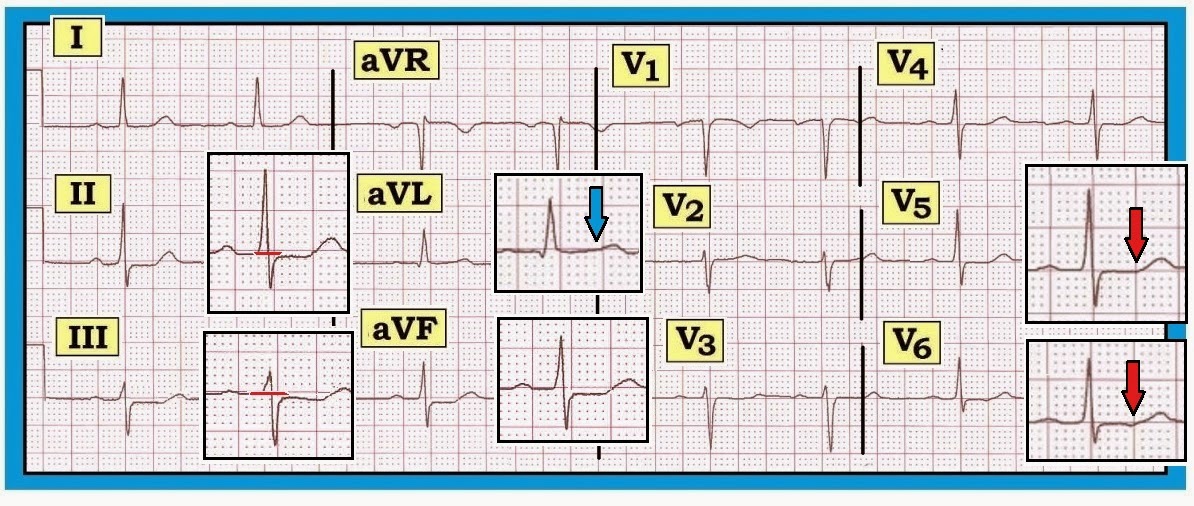
     Interpret the ECG shown in Figure-1 — obtained from an adult with a recent history of atypical chest discomfort.
  • Would you classify the ECG shown in Figure-1 as a “normal” tracing?
  • If not — Why not?

Figure-1: ECG obtained from an adult with atypical chest discomfort. Would you interpret this ECG as a “normal” tracing? 


------------------------------------------
Interpretation of Figure-1: The rhythm is sinus bradycardia and arrhythmia (heart rate ~60/minute, or a bit below this). The PR, QRS and QT intervals are all normal — as is the axis (which is about +30 degrees). There is no chamber enlargement.
  • Q-R-S-T Changes: A small and narrow q wave is seen in lead aVL. Transition is slightly delayed (the R wave becomes taller than the S wave is deep between V4-to-V5). The most remarkable finding on this ECG is ST segment flattening with slight ST depression in multiple leads.
  • The amount of actual ST segment depression on this tracing is minimal (no more than 1mm in the inferior leads) — yet there is no denying that ST depression is present (See blow-up inserts in the inferior leads in Figure-2).
  • There is no ST depression at all in leads I and V2-thru-V6 (Figure‑2). That said — ST-T waves are not normal in these leads. Instead — there is subtle-but-real ST segment straightening that resembles the picture in Panel B of Figure‑3.

BOTTOM Line: The ECG in Figure-2 is not normal. Instead — there is diffuse nonspecific ST flattening and slight ST depression. These changes are subtle but real. Clinical correlation is essential for knowing how to interpret this ECG finding. This patient may have coronary disease — possibly even severe coronary disease. On the other hand — these changes are not acute and they could be due in part or in combination to any of the other potential causes of ST depression (drug effect, electrolyte disorder, hyperventilation, acutely ill patient, etc.). We simply cannot tell on the basis of this single ECG.

Figure-2: Reproduction of the ECG in Figure-1, with blow-up inserts illustrating subtle ST-T wave abnormalities. Note that there is ST depression (of ~1mm) in the inferior leads. There is also ST segment flattening (straightening) but no depression in leads I and V2-thru-V6 (red arrows in blow-up inserts in V5,V6). Although T wave amplitude in lead aVL is reduced — note that gradual transition from ST segment-to-T-wave is preserved in this lead (blue arrow) — compared to clear straightening of the ST segment in leads V5,V6 (red arrows). This is not a “normal” ECG. 


------------------------------------------
Recognizing Subtle ST Changes: ST Segment Straightening
Consensus among expert electrocardiographers is lacking regarding the definition of a “normal” ECG. Much of this relates to semantics — since minor ST‑T wave abnormalities generally provide no more than a nonspecific suggestion to potential etiologies. That said — We feel it is important to hone in on recognizing even minimal abnormalities, if for no other reason than to let those reading our interpretation be aware that we saw the abnormality in question but did not think it clinically important for the case at hand.
  • The above said — there are times when even minimal ST-T wave changes may have clinical relevance. In addition — routine attention to recognizing subtle ST-T wave changes will go a long way toward improving one’s ECG interpretation ability.
  • For example — What is the difference between the ST segment shown in Panel A vs Panel B in Figure-3? Is the admittedly subtle difference in ST‑T wave appearance between these two complexes likely to be of clinical significance? If so — How?

Figure-3: Compare the ST segment in Panel A with Panel B. What is the difference? Is this likely to be clinically significant?


------------------------------------------
Answer to Figure-3: The ST-T wave in Panel A is normal. Note the smooth contour at the point of transition between the end of the S wave and the beginning of the ST segment. Note an equally smooth contour at the end of the ST segment and the point where the ascending limb of the T wave begins.
  • In contrast — Note the sharp angle in Panel B at the point where the straight (flat) ST segment ends and the ascending limb of the T wave begins (red arrow). While admittedly “splitting hairs” — the ST-T wave in Panel B is not normal. Instead — there is nonspecific ST segment straightening (ie, loss of that smooth transition between end of the ST segment and the beginning of the T wave ascending limb).
  • We emphasize that “nonspecific ST segment straightening” — is a descriptive finding. It is nonspecific. It may mean nothing — especially if only seen in a single lead. In any case — it is not an acute change. On the other hand — ST segment straightening as occurs in Panel B may at times be a nonspecific indicator of underlying coronary disease — especially when this finding is seen in more than one lead. Clinical correlation is everything.

-------------------------------------
- For more information — GO TO:
  • For a pdf of Section 09.0  — on ST-T Wave Changes (from our ECG-2014-ePub).
-------------------------------------

Sunday, February 2, 2014

ECG Blog #83 — Every-Other-QRST is Different

     Interpret the 3-lead rhythm strip shown in Figure-1 — obtained from a patient in a fairly (but not completely) regular SVT rhythm.
  • What is the reason for the slight change in QRS morphology from beat-to-beat?

Figure-1: 3-lead rhythm strip — obtained from a patient in a regular SVT rhythm. What is the reason for the slight change in QRS morphology from beat-to-beat? 


Answer to Figure-1: 
Although one might at first be tempted to interpret the rhythm as a form of bigeminy — a more accurate interpretation would be electrical alternans. While we would accept general description of this rhythm as representing a “regular” SVT (SupraVentricular Tachycardia) — there is in fact slight-but-real phasic variation in the R‑R interval occurring every-other-beat. This is not due to a form of bigeminy — but rather to R‑R alternans. In addition — there is both QRS alternans (red and blue double arrows in Figure-2) — and T wave alternans (red and blue circles in Figure-2). That is — QRS morphology changes every-other-beat. This is subtle in lead V1 — but more noticeable in lead V2 where the initial R wave manifests an obvious difference in height from one beat to the next. Similarly — T wave morphology changes every-other beat, with this clearly more noticeable in lead V2 which manifests extra peaking of every-other-T wave (red and blue circles in lead V2).
  • Clinical implications of these forms of electrical alternans in a patient with SVT — are that reentry is almost certain to be involved in the mechanism. There may or may not be a concealed accessory pathway.

Figure-2: We have labeled the 3-lead rhythm strip recorded in Figure-1. There is slight shortening of the R-R interval every-other beat = R‑R alternans. In addition — there is both QRS alternans (red and blue double arrows) — and T wave alternans (red and blue circles in Figure-2). That is — QRS and T wave morphology changes every-other-beat.


What is Electrical Alternans?
The fascinating phenomenon of electrical alternans — is a relatively uncommon clinical entity that is frequently misunderstood. It is often overlooked when it does occur. A look at Figure-1 explains why: This ECG sign can be subtle indeed.
  • Electrical alternans is a general term that encompasses a number of different pathophysiologic mechanisms. Its occurrence is not limited to pericardial tamponade — but instead has been associated with an expanding array of clinical conditions.
  • Distinction should be made between electrical and mechanical alternans. The term “alternans” itself — merely indicates that there is phasic fluctuation in some cardiac signal from one beat to the next within the cardiac cycle. This may be in the strength of the pulse (or the blood pressure recorded) — or it may be in one or more waveforms in the ECG recording.
NOTE: It may be helpful to first define other alternans phenomena that may sometimes be confused with the various ECG manifestations (especially since these other forms of alternans phenomena may also be seen with cardiac tamponade).
  • Pulsus alternans — is a mechanical form of alternans. The rhythm is regular — but cardiac output varies from beat-to-beat. It is seen with severe systolic dysfunction. Pulsus alternans should be distinguished from a bigeminal pulse — in which a weaker beat follows the stronger beat by a shorter time interval (as occurs when the alternating beat is a PVC, which understandably generates less cardiac output).
  • Pulsus alternans should also be distinguished from pulsus paradoxus — in which there is a palpable decrease in pulse amplitude (or a measured drop of >10mm in blood pressure) during quiet inspiration. While pulsus alternans and paradoxus may both be seen with pericardial tamponade — they are different phenomena than the various types of electrical alternans.


Electrical Alternans: Definition/Features/Mechanisms
Electrical alternans — is a beat-to-beat variation in any one or more parts of the ECG recording. It may occur with every-other-beat — or with some other recurring ratio (3:1; 4:1; etc.). Amplitude or direction of the P wave, QRS complex, ST segment and/or T wave may all be affected (although P wave alternans is rare). Alternating interval duration (of PR, QRS or QT intervals) may also be seen.
  • Electrical alternans — was first observed in the laboratory by Herring in 1909. It was reported clinically by Sir Thomas Lewis a year later, who characterized the phenomena as occurring, “either when the heart muscle is normal but the heart rate is very fast or when there is serious heart disease and the rate is normal”. This 1910 description by Lewis serves well to this day to remind us of the 2 principal clinical situations in which electrical alternans is most often encountered: i) Supraventricular reentry tachycardias; and ii) Pericardial tamponade.

Mechanisms: 
There are 3 basic types of electrical alternans phenomena — each relating to a different pathophysiologic mechanism: i) Repolarization alternans; ii) Conduction and Refractoriness alternans; and iii) Alternans due to abnormal cardiac motion. A common cellular mechanism may underlie each of these processes relating to abnormal calcium release or reuptake within the sarcoplasmic reticulum.
  • Repolarization alternans — entails beat-to-beat variation in the ST segment and/or T wave. Alternation in ST segment appearance (or in the amount of ST elevation or depression) — is often linked to ischemia. In contrast — T wave alternation is more often associated with changes in heart rate or in QT duration (especially when the QT is prolonged). In patients with a long QT — T wave alternans may forebode impending Torsades de Pointes. Both ST segment and T wave alternans have been known to precede malignant ventricular arrhythmias. Thus, this type of electrical alternans may convey important adverse prognostic implications when seen in certain situations. That said — a variety of clinical conditions have been associated with repolarization alternans, such that adverse prognostic implications do not always follow. Among these clinical conditions are congenital long QT syndrome — severe electrolyte disturbance (hypocalcemia; hypokalemia; hypomagnesemia) — alcoholic or hypertrophic cardiomyopathy — acute pulmonary embolus — subarachnoid hemorrhage — cardiac arrest and the post-resuscitation period — and various forms of ischemia (spontaneous or induced by treadmill testing or other stimulus).
  • Conduction and Refractoriness alternans — entails variance of impulse propagation along some part of the conduction system. This may result from fluctuations in heart rate or in nervous system activity or from pharmacologic treatment. ECG manifestations from this form of alternans may include alternating appearance of the P wave, QRS complex or alternating difference in P-R or R-R interval duration. In particular — QRS alternans during narrow SVT rhythms has been associated with reentry tachycardias. While identification of QRS alternans during a regular SVT often indicates retrograde conduction over an AP (Accessory Pathway) — this phenomenon has also been seen in patients with simple PSVT/AVNRT that exclusively limits its reentry pathway to the AV Node. Therefore — identification of QRS alternans during a regular SVT does not prove the existence of an accessory pathway. Conduction and refractoriness alternans may be seen with WPW-related as well as AV Nodal-dependent reentry tachycardias — atrial fibrillation — acute pulmonary embolus — myocardial contusion — and severe LV dysfunction. NOTE: On occasion — Alternans may be seen with monomorphic VT (Maury and Metzger).
  • Cardiac Motion alternans — is the result of cardiac movement rather than electrical alternation. The most important clinical entity associated with motion alternans is large pericardial effusion — though motion alternans has also been observed in some cases of hypertrophic cardiomyopathy. It is important to appreciate that not all pericardial effusions produce electrical alternans. Development of total electrical alternans (of P wave, QRS complex and T wave) — is likely to be a harbinger of impending tamponade. Unfortunately — the sensitivity of total electrical alternans is poor for predicting tamponade (ie, most patients who develop tamponade do not manifest preceding electrical alternans). Therefore — it may be helpful if you see total electrical alternans in a patient with a large pericardial effusion — but failure to see this ECG sign in no way rules out the possibility that tamponade is occurring. Echo studies in patients with documented cardiac tamponade confirm that electrical alternans is synchronous with and a direct result of the pendulous movement of the heart within the enlarged, fluid-filled pericardial sac of a patient with large pericardial effusion.


Electrical Alternans: KEY Clinical Points
In summary, electrical alternans is not common — but it does occur. You will see it. You have probably already seen it a number of times without even realizing it. Electrical alternans is a fascinating but advanced concept.
  • In our experience — electrical alternans is most often seen in association with regular SVT rhythms (as seen in Figure-1). Seeing it in this context suggests (but does not prove) the existence of an AP (Accessory Pathway). Regardless of whether the mechanism of the regular SVT is AVNRT or AVRT — it is likely that reentry is involved. This conclusion may prove useful in contemplating potential investigative and therapeutic interventions.
  • In a patient with pericarditis — a large heart on chest X-ray — or simply unexplained dyspnea — recognition of electrical alternans should suggest the possibility of a significant pericardial effusion that may be associated with tamponade. That said — electrical alternans is a nonspecific ECG sign that may also indicate myocardial ischemia, LV dysfunction and/or possibility of any of a number of other precipitating factors. BOTTOM Line: If you see electrical alternans — Look for an underlying clinical condition that may be responsible for this ECG sign.
  • Development of electrical alternans per se — conveys no adverse prognostic implications beyond those associated with severity of the underlying disorder. Two exceptions to this general rule are: i) In a patient with QT prolongation or severe ischemia — recognition of electrical alternans may portend deterioration to Torsades or VT/VFib; and, ii) In a patient with a large pericardial effusion — development of total electrical alternans (of P wave, QRS complex and T wave) suggests there may now be tamponade.
  • P.S. — Keep in mind that not all cases of pericardial effusion will manifest low voltage and electric alternans ... (The pathophysiology behind electrical alternans with a large pericardial effusion — is a "swinging heart" within the pericardial sac. Thus, alternans is unlikely to be seen with smaller effusions — and even with larger effusions, not all cases manifest alternans ...).

-------------------------------------
ACKNOWLEDGMENT: My appreciation to Jenda Enis Stros for allowing me to use the ECG in Figure‑1.
-------------------------------------

- For more information — GO TO:

  • For a pdf of Section 14.0  — on Electrical Alternans (from our ECG-2014-ePub).
-------------------------------------